
STM32 Blinking LED
Every microcontroller needs a way to talk to the outside world — that’s where I/O ports come in. The STM32 has several banks of General Purpose Input/Output (GPIO) ports, named GPIOA, GPIOB, GPIOC, and so on.
Each port can have up to 16 pins, numbered Px0–Px15 (where x is the port letter). Not every pin can do everything, and not every port can be fully configured as analog — the available modes depend on the chip’s internal peripheral mapping. But in general, pins can be set as:
Input – to read buttons, switches, or sensors
Output – to drive LEDs, relays, or other devices
Alternate Function – built-in peripherals like timers, serial ports, or I²C buses
Analog – for ADC readings or DAC outputs (only on pins that support it)
In this tutorial, we’ll make our STM32 Nucleo-L476RG use both an input and an output:
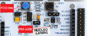
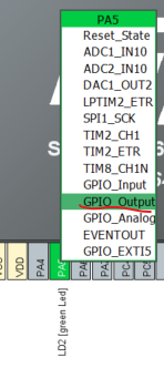
PA5 – Output mode to blink the onboard LED (LD2)
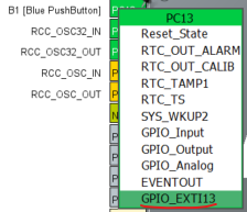
PC13 – Input mode with an interrupt to detect the onboard pushbutton (B1)
Rather than blink at a fixed speed, our program will change the blink rate each time the button B1 (PC13) is pressed, cycling through slow, medium, and fast modes. This will enable us to: configure pins using the graphical pinout tool, use interrupts for event-driven input, and write simple control logic to manage different states.
By the end, you’ll have your first STM32 program that reacts to input and controls an output — a solid foundation for every more advanced project in this series. But first lets talk about Development Flow.
STM32 Development Flow
When you write a project for the STM32, there’s a fairly standard process:
Start with an Idea
Decide what you want the microcontroller to do — in this case, blink an LED at different speeds depending on button presses.
Configure the Hardware in the Pinout View
STM32CubeIDE includes a graphical configuration tool where you can select your MCU or board, then click on pins to set their function (input, output, alternate function, analog).
This is where you tell the chip, “PA5 will be an output” or “PC13 will be an external interrupt input.”
Generate the Project Skeleton
Once pins and peripherals are configured, STM32CubeIDE generates all the initialization code for you — clock setup, GPIO setup, interrupt wiring — so you don’t have to hand-code those basics.
Write Your Application Logic
This is where your code goes — toggling pins, reading sensors, calculating values, controlling devices, etc.
Build and Flash the Program
Compile your code into machine language, then use the built-in ST-LINK debugger/programmer to load it onto the board
Test and Debug
Run the code, watch what happens, and fix anything that doesn’t match your plan
For our Blink with Button Interrupt example, we’ll follow exactly this process:
Step into Pinout & Configuration to set PA5 as an output and PC13 as an interrupt input.
Generate the
.iocproject skeleton.Add our blink and button handling logic to
main.c.Build, flash, and watch the LED respond to button presses.
The next 3 sections (Pin Mapping with the GUI, Program Development, and Test), will consist of these steps in this section, and should summarize the general design flow for STM32 systems.
Pin Mapping with The GUI
Before we write a single line of application code, we need to tell the STM32 which pins will be doing what. STM32CubeIDE makes this painless with the Pinout & Configuration GUI. Instead of digging through datasheets and manually writing initialization code, we can simply click on a pin in the graphical MCU diagram and assign it a role — input, output, alternate function, or analog.
When we set up our pins and peripherals in this view, CubeIDE stores all of those settings in a project configuration file with the extension .ioc (short for I/O Configuration). This file is more than just a record of what we clicked — it’s the blueprint the IDE uses to automatically generate the initialization code for our project.
The .ioc file tells CubeIDE things like:
Which pins are inputs or outputs
Which peripherals are enabled and how they’re configured
What clock settings the chip should use
How interrupts are routed
When we click Generate Code, CubeIDE reads the .ioc file and creates a complete code framework:
Peripheral initialization functions (
MX_GPIO_Init(), etc.)Correct clock setup based on our choices
Interrupt vectors linked to our configured pins
This means we can focus on writing our application logic while letting the IDE handle the boilerplate setup. If we need to change a pin later, we can update the .ioc file and regenerate the code — just keep in mind that any changes made outside the USER CODE sections in the generated files will be overwritten. The USER CODE sections are denoted with comments in the code. For quick experiments, you can also edit the initialization code manually, but those edits won’t be preserved if you regenerate from .ioc.
In short: the .ioc file is the bridge between your hardware configuration in the GUI and the auto-generated startup code that gets your STM32 ready to run your program.
Before we dive into the Pinout view, it’s important to understand that the .ioc configuration isn’t just a convenience — it’s the blueprint for all of the initialization code CubeIDE generates. Every pin mode, peripheral setting, and clock configuration you define here is directly reflected in the generated source files. If you’re reusing code from another project, your .ioc setup must match the hardware configuration that code expects, or the program may compile but won’t behave correctly. Think of the .ioc file as the single source of truth for the hardware setup: change it, and the underlying initialization code changes with it.
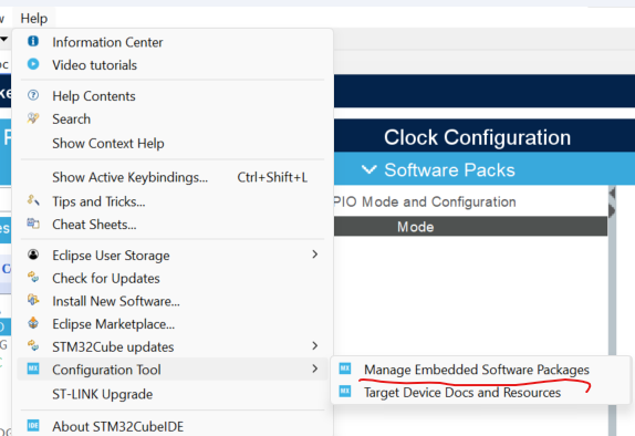
Open STM32CubeIDE, and after it opens, Click on Manage Embedded Software Packages, which can be found under the Configuration Tool tab under Help, shown below.
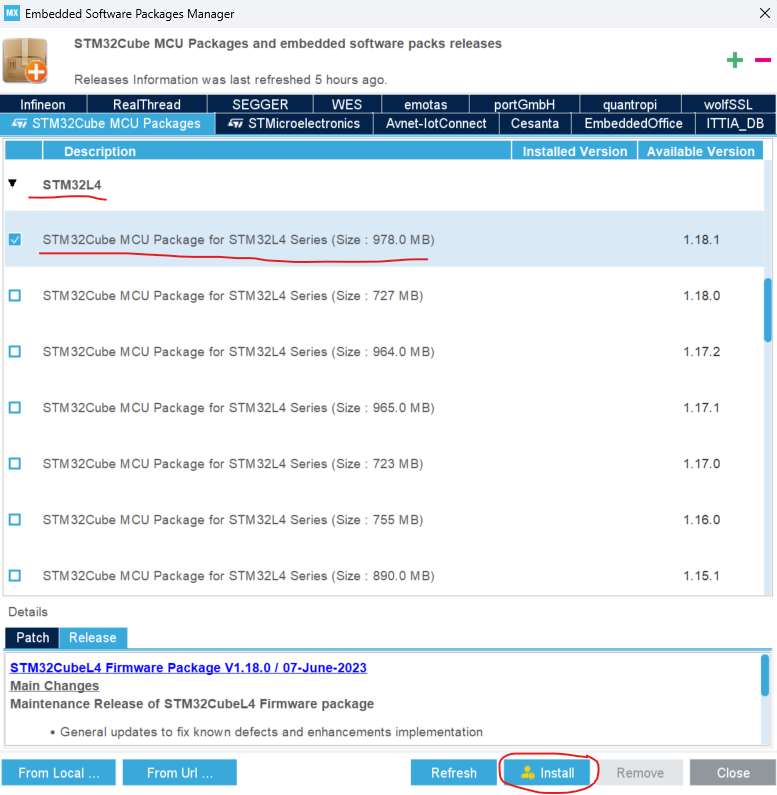
The Embedded Software Package Manager box should appear. Select the STM32Cube MCU Packages tab, and under STM32L4 selelect the latest package listed below as 1.18.1, yours might be newer. Click Install.
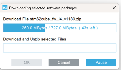
The software package will begin downloading and installing. You might be asked to agree to a license agrrement, just accept the terms and move on.
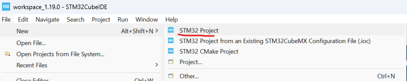
Once you're finished installing the software package create a project, as shown below.
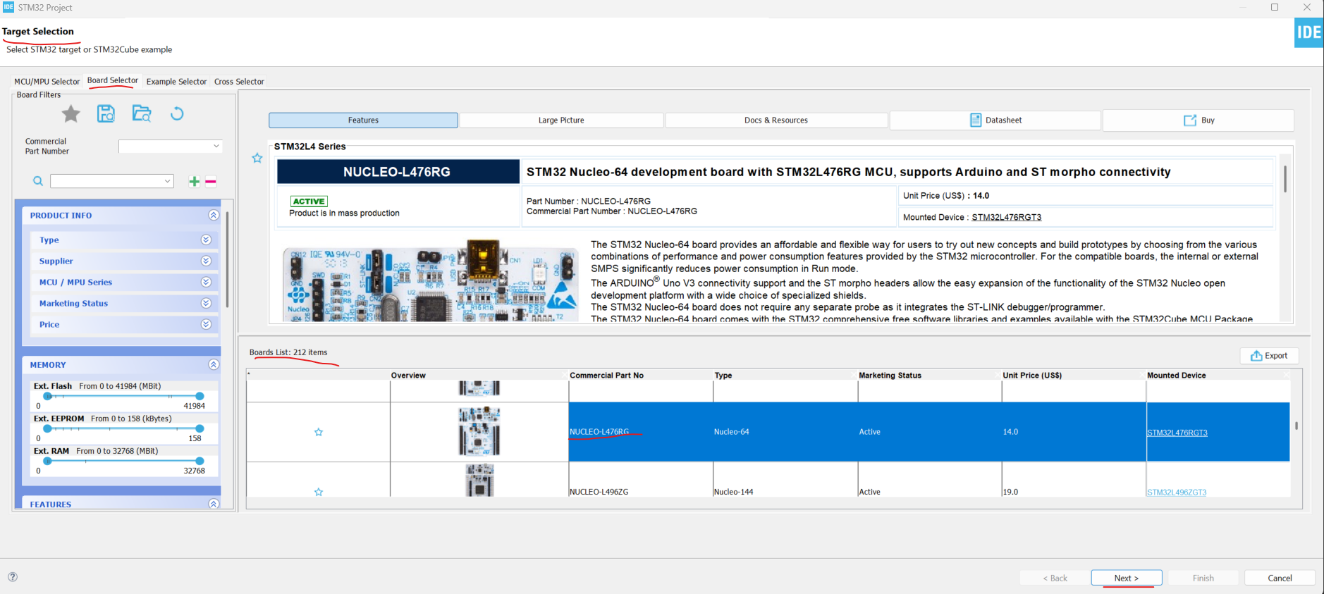
Select a board by clicking the Board Selector tab and scrolling down to NUCLEO-L476RG, click on that board and press Next. This is the board used in this tutorial. You can use a different Nucleo board if you have one, but be aware that things may look different — and some settings will likely need to change.
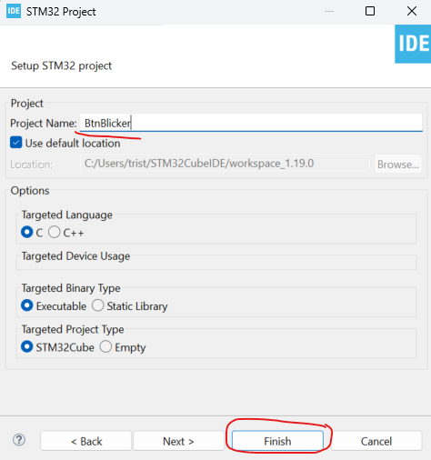
Name the project (you can use the default settings for everything else) and click Finish..
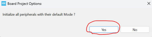
When prompted, select Yes to “Initialize all peripherals with their default mode,” as shown below.
You should now see the MCU Pinout & Configuration tab in its default state, as shown below.
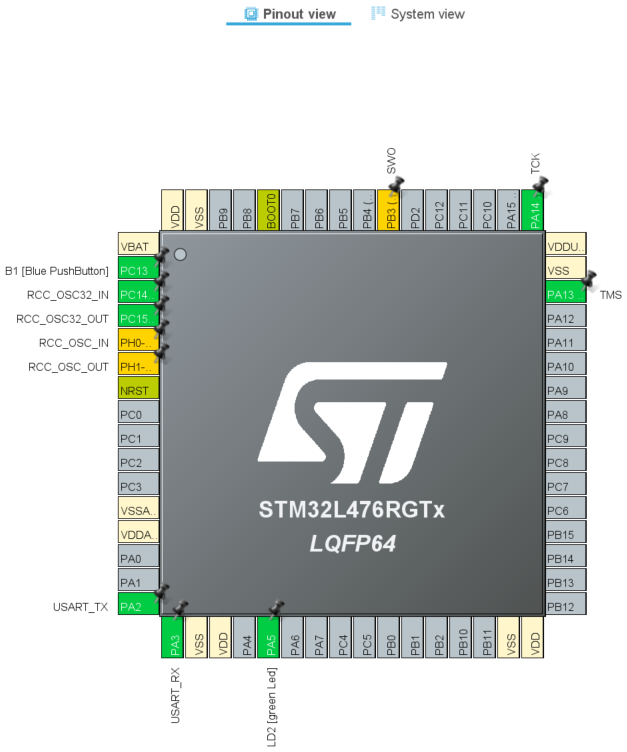
Click on the PA5 pin to confirm that PA5 (the onboard LED pin, LD2) is set to GPIO_Output. This is the default configuration, but it’s always good practice to double-check.
Confirm that PC13 (the onboard user button, B1) is set to GPIO_EXTI13. This configuration enables an external interrupt on the button pin, which we’ll use in the program.
In the Configuration pane, expand System Core → GPIO and review the settings. Confirm that PA5 is listed as an output and PC13 is listed as an external interrupt input.
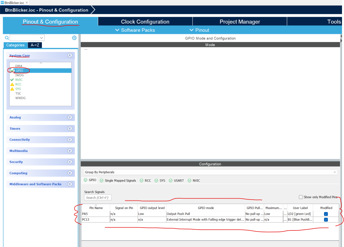
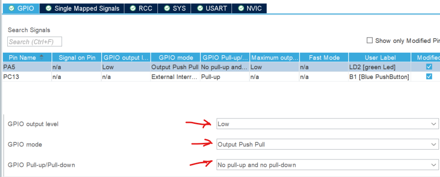
Click on the PA5 row and ensure that it has the following valus as shown below.
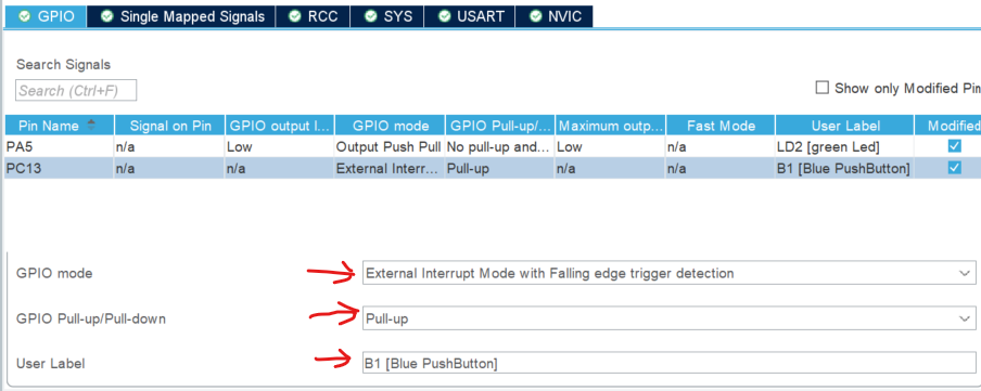
Now click on PC13 and ensure it has the following values.
Now click on the NVIC tab and make sure the Enable column is checked as shown below.

Save and click Generate Code.
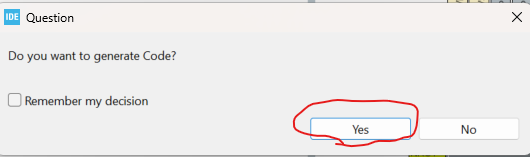
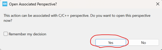
YOu should get a messge like the one below, just clcik ok
At this point you should see some code and files generated in the Project Explorer, as shown below.

Congrats we're now in the Program Development stage!
Program Development
With our pins configured in the .ioc file and the initialization code generated, we can now move on to writing the application logic itself. The heavy lifting of setting up clocks, GPIO modes, and interrupts has already been handled by CubeIDE — all that remains is to tell the microcontroller what to do inside our program.
In this section, we’ll open up the generated main.c file and add code inside the designated USER CODE blocks. These areas are reserved for our custom logic, and unlike the auto-generated portions of the project, they won’t be overwritten if we regenerate code later.
Our goal is simple:
Toggle the LED on PA5.
Use the button on PC13 to step through different blink speeds.
Demonstrate how interrupts can be used to make the system respond immediately to input events.
By the end of this section, you’ll have your first working STM32 application that ties the hardware configuration to real behavior on the board.
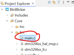
Open
main.cIn the Project Explorer, expand Core → Src and double-click
main.c. This is the main entry point for your application.
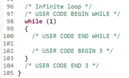
Locate the
while (1)loopScroll down until you see the infinite loop. Notice the
/* USER CODE BEGIN WHILE */and/* USER CODE END WHILE */markers — this is where we’ll add our blinking logic. An example of what to look for is shown below.
Add global variables
At the top of the file, inside
/* USER CODE BEGIN PV */, add the variables to track the blink speed:
Add the interrupt callback
Scroll down to the
/* USER CODE BEGIN 4 */section and add the button handler:
Add the LED blink logic
Back in the
while (1)loop, insert the LED toggling code:
Code WalkThrough (What, Why, and How)
When CubeIDE generated the project, it gave us the startup code. At the top of main.c, the call to HAL_Init() prepares the chip and starts the system tick timer that HAL_Delay() uses. Right after that, SystemClock_Config() sets the system clocks so the CPU and peripherals all run at the right speeds. The third key function, MX_GPIO_Init(), applies the pin settings from the .ioc file. That means PA5 is set as an output for the LED, and PC13 is linked to EXTI line 13 so it can trigger an interrupt when the button is pressed.
Let’s follow what happens when you push the button. The falling edge on PC13 raises an interrupt on EXTI line 13. That request goes into the NVIC — the Nested Vectored Interrupt Controller. The NVIC is the Cortex-M’s traffic cop, deciding which interrupts run and when. Since CubeIDE enabled the grouped EXTI15_10 interrupt, the NVIC accepts the request and calls EXTI15_10_IRQHandler() in stm32l4xx_it.c. From there, the HAL takes over with HAL_GPIO_EXTI_IRQHandler(GPIO_PIN_13), and finally your own callback HAL_GPIO_EXTI_Callback() runs. Inside that function you wrote, blinkMode is incremented so the program steps to the next blink speed.
The program state is managed by two variables you added earlier. blinkMode tells the program which speed is active, and blinkRates[] stores the actual delay values in milliseconds. Marking blinkMode as volatile is important, because it gets changed inside an interrupt and the compiler needs to know not to optimize it away.
Now look at the main loop. The call to HAL_GPIO_TogglePin(GPIOA, GPIO_PIN_5) flips the LED each time the loop runs. The call to HAL_Delay(blinkRates[blinkMode]) then pauses for the correct amount of time, based on which mode you’re in. Because HAL_Delay() uses the SysTick timer set up by HAL_Init(), it gives you an easy millisecond delay without extra configuration.
Altogether, the auto-generated init functions set up the hardware, the NVIC routes the interrupt, the HAL gives you simple functions to work with, and your small state machine ties it together. The end result is exactly what you see on the board: an LED that blinks at different speeds, with each button press immediately changing the mode.
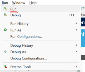
Test It!
With the code written and generated, it’s finally time to hit Run and let the Nucleo do its thing. Flash the board, and you should see LD2 blinking away — one press of the blue button cycles it slower, another press makes it faster, and so on. For the first time in this series, you’ve got input (the pushbutton), output (the LED), and interrupts (EXTI/NVIC) all working together in a real application
That’s not just a blinking LED anymore — it’s proof your toolchain is alive, your .ioc setup is solid, and your code is running where it should. Consider this your STM32 “hello world,” and enjoy the little victory: your board just listened, reacted, and lit up on command. 🎉
Good luck on your endeavors!