
ADC+Pot Read → OLED
Every microcontroller project eventually needs to move past “blinky lights” and start showing useful information. For that, we need two things: a way to measure something from the real world, and a way to display it in a form humans can understand.
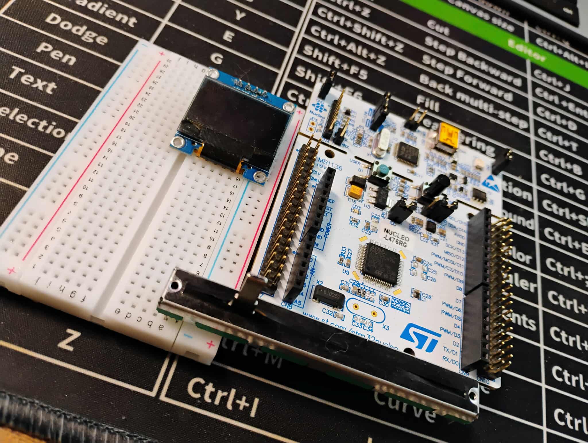
Here’s the hardware breakdown:
ADC Input (e.g., PA0) – reads the voltage from a slider potentiometer.
I²C Bus (PB8 = SCL, PB9 = SDA) – drives the GME12864 OLED display.
Our program will start by showing a the voltage on a potentiometer, then switch to my logo on the OLED. Moving the potentiometer and changing the ADC voltage will display the voltage on the OLED, after a brief period the display will switch back to the logo . That means you’ll learn how to
Configure an STM32 pin for analog input and read it with the ADC.
Set up the I²C peripheral to talk to the OLED.
Initialize and control a graphical display.
By the end, you’ll have a project that feels alive: turning a knob changes the number on the screen. This is where the STM32 stops just blinking and starts communicating — a big step toward full-featured embedded applications.
Equipment
Below is a list of the equipment you'll need to do this tutorial. There's also a picture that shows all the hardware you need - minus the jumper wires.
STM32 Nucleo-L476RG board (or compatible Nucleo with ADC + I²C)
10kΩ potentiometer (slider or rotary)
GME12864 OLED display (I²C interface)
Breadboard + jumper wires
USB cable (for power + programming via STM32CubeIDE)
STM32CubeIDE
The GME12864 OLED Display
The GME12864 is a 128×64 pixel monochrome OLED module. Unlike a simple character LCD (where you just send ASCII letters), this display doesn’t know anything about text or graphics by itself — it only knows pixels. If you want to show “Hello World,” you’re really turning on and off the right pixels until the words appear.
The module we’re using talks to the STM32 over I²C:
SDA carries the data.
SCL carries the clock signal.
Inside the OLED is a small controller chip whose job is to keep the pixels lit once you tell it what to draw. To make it work, we send two kinds of information over I²C:
Commands — things like “turn the display on,” “set contrast,” or “move to this column.”
Data — the raw pixel map (which pixels are on vs. off).
A few practical facts about this display:
Resolution: 128 columns × 64 rows of pixels.
Color: Monochrome (each pixel is either on or off).
Layout: The screen is divided into small blocks of pixel memory called “pages,” and we update the screen by sending new page data over I²C.
Because the OLED only understands pixel maps, any image you want to show — like a logo — must be converted into a 1-bit bitmap first. That’s why our development flow includes a dedicated Image Processing step: we’ll resize a logo, convert it to black-and-white, and export it as a C array the STM32 can push straight to the OLED
One more important piece: the OLED must be initialized before it will display anything. On power-up, the controller chip inside the GME12864 is basically in “sleep mode.” Our code will send it a series of commands over I²C that configure the contrast, set the addressing mode, and finally turn the display on. You don’t need to memorize these commands — the initialization routine is provided — but keep in mind that nothing will appear on the screen until this initialization happens.
Once you’ve done that, the OLED becomes a little digital canvas. You can write numbers, text, waveforms, or graphics — all by arranging the right pixels.
STM32 Development Flow
When you dive into a project on the STM32, there’s a pretty reliable rhythm you’ll follow. First comes the idea — the “wouldn’t it be cool if…” moment. For this tutorial, the cool factor is cranking a potentiometer, watching the STM32 measure that voltage, and then seeing the result light up on an OLED screen. To top it off, a single button press will flip the display between your custom logo and the live voltage readout — like giving your microcontroller its own little personality switch.
Our general flow is below.
Start with an Idea
Decide what you want the microcontroller to do — in this case, read an analog voltage from a potentiometer, display the value on an OLED screen, and allow a button press to toggle between your logo and the live readout
Configure the Hardware in the Pinout & Configuration View
This is where you tell the chip, through the .ioc GUI, what it's pins will be doing.
“PA0 will be an ADC input.”
“PB8 and PB9 will be I²C pins for the OLED.”
Project Code Generation (the .ioc magic)
Once the pinout and peripherals are set, CubeIDE builds the foundation for you. With one click, it generates the initialization code: clocks, GPIO, ADC drivers, I²C wiring, and interrupt hookups. Think of it as CubeIDE handing you a clean workbench so you can focus on the fun part — your logic.
Write Your Application Logic
Now you add the brains: reading the ADC, converting digital counts into volts, pushing data to the OLED, and reacting to button presses to flip between display modes.
Build and Flash the Program
Hit compile, let the toolchain spit out machine code, and send it over to the board with the built-in ST-LINK.
Test and Debug
Run it, watch the OLED, twist the knob, hit the button, and confirm the system behaves like you planned.
For our OLED + ADC + Toggle Display example, we’ll follow exactly this process:
Process the logo image into a format the OLED library understands (resize, convert to monochrome, export as a C array).
Step into Pinout & Configuration to set PA0 as ADC input, and PB8/PB9 as I²C for the OLED.
Run Project Code Generation to create the
.iocskeleton with all the init code.Add our ADC read, OLED display, image render, and toggle logic to
main.c.Build, flash, and watch the OLED flip between your logo and a live voltage readout with each button press.
The next 4 sections (Image Processing, Pin Mapping with the GUI, Program Development, and Hookup & Test) will walk through these steps in detail and summarize the general design flow for STM32 systems.
Image Processing
The OLED doesn’t know what to do with a PNG or JPG. All it understands is on/off pixels packed into bytes, so if you want to put your logo on screen, you need to turn it into a 1-bit bitmap C array first.
Instead of firing up GIMP or hunting for random converters, we’ve built a tool right here in the tutorial. Make sure you use a pretty basic image, otherwiase the liekness might not be apparent.
How to use it:
Upload your logo (or any simple image)
Set the target size (usually 128×64).
Pick Threshold (clean, sharp edges) or Floyd–Steinberg (dithered detail).
Adjust the threshold slider if needed.
Click Convert.
You’ll see a live preview of your image in 1-bit mode and a ready-to-use C header file. Copy the array or download the .h file, then drop it into your STM32CubeIDE project.
From there, the OLED driver code can draw it just like any other bitmap.
Pin Mapping with The GUI
Before we can light up a single pixel on the OLED, we’ve got to tell the STM32 how it’s wired to the outside world. Thankfully, CubeIDE makes this less of a datasheet scavenger hunt and more of a point-and-click adventure with its Pinout & Configuration GUI.
Instead of hand-coding every register and triple-checking the reference manual, we just click the pins in the graphical MCU diagram and assign them a purpose: I²C lines for the OLED, an analog input for the potentiometer, and maybe a button for screen toggling.
All of these clicks get saved in a special project file called .ioc (short for I/O Configuration). Think of it as your hardware blueprint — the file that tells CubeIDE which pins do what, which peripherals are alive, what the clocks look like, and how interrupts are routed.
When you hit Generate Code, CubeIDE translates that .ioc file into a ready-to-run framework:
Peripheral init functions (
MX_I2C1_Init(),MX_ADC1_Init(), etc.)Correct clock tree setup
Proper interrupt vectors and handlers
GPIO initialization baked in
That means you can stop worrying about boilerplate setup and start focusing on the fun stuff — like drawing your logo on the OLED. Need to change a pin or peripheral later? Just update the .ioc, regenerate, and the code adapts. (Pro tip: always keep your edits inside the USER CODE sections, or they’ll vanish faster than your coffee supply during an all-nighter.)
In short: the .ioc file is the single source of truth for your STM32 hardware setup. Treat it as the map that guides CubeIDE in generating all the startup glue you’d otherwise be writing by hand. Get this step right, and the rest of your OLED adventure goes a whole lot smoother.
Note: we do not set the I2C address for the OLED in the steps below! Provided it's the only I2C device on the line, we will find the address in code, so you don't have to know it now.
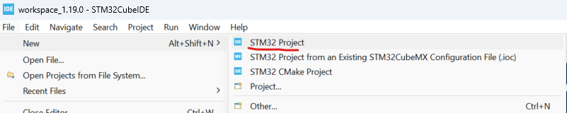
Open STMCubeIDE, and create a project, as shown below.
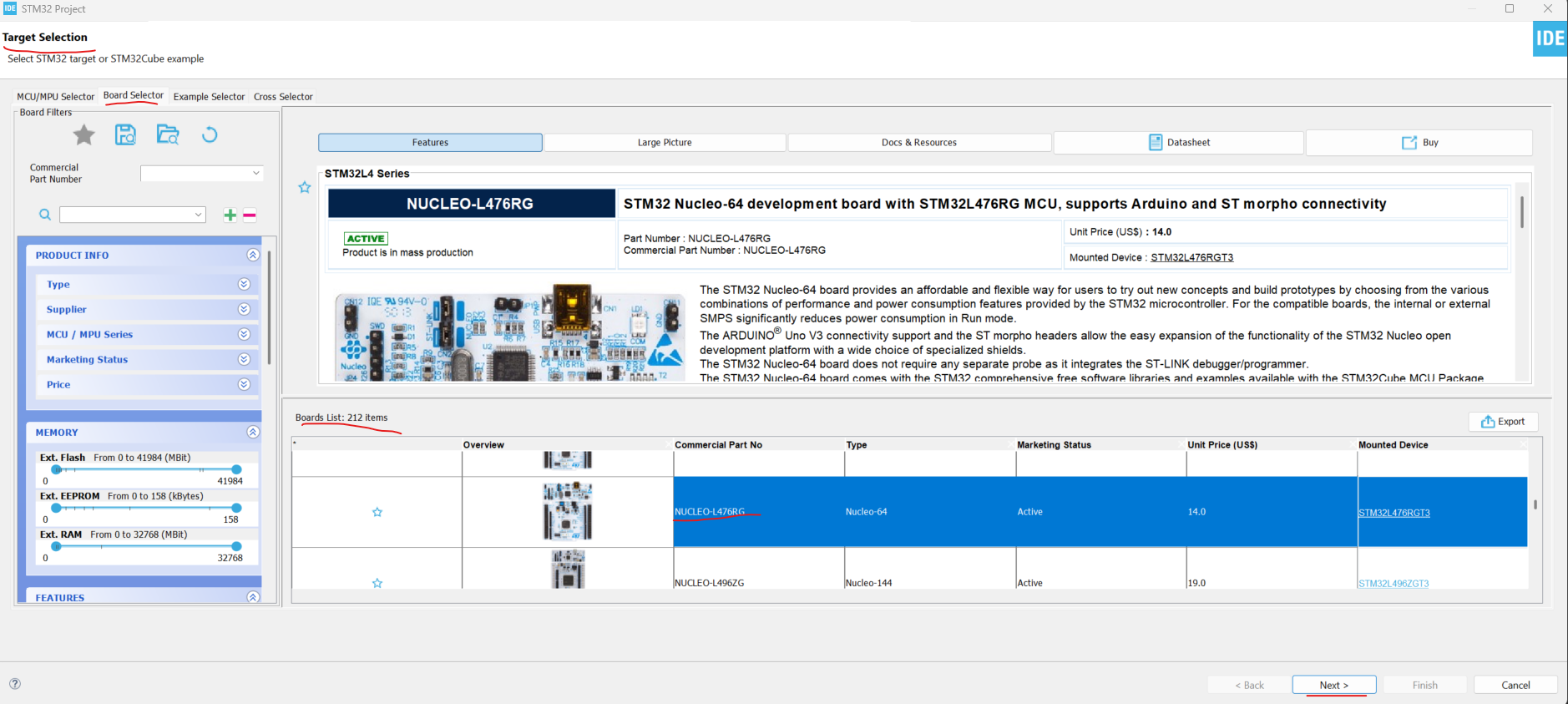
Select a board by clicking the Board Selector tab and scrolling down to NUCLEO-L476RG, click on that board and press Next. This is the board used in this tutorial. You can use a different Nucleo board if you have one, but be aware that things may look different — and some settings will likely need to change.
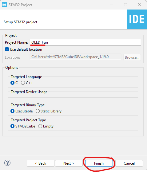
Name the project (you can use the default settings for everything else) and click Finish..
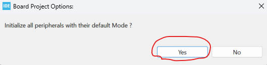
When prompted, select Yes to “Initialize all peripherals with their default mode,” as shown below.
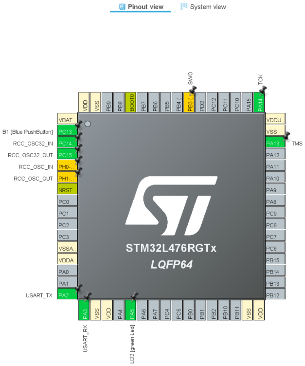
You should now see the MCU Pinout & Configuration tab in its default state, as shown below.
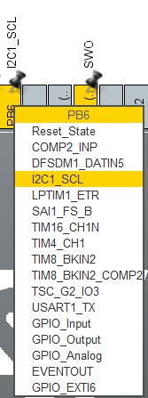
Click on the PB6 pin and select I2C1_SCL, as shown below.
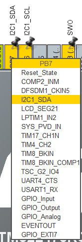
Click on the PB7 pin and select I2C1_SDA.
Click on the PA0 pin, and select ADC_IN5.
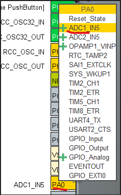
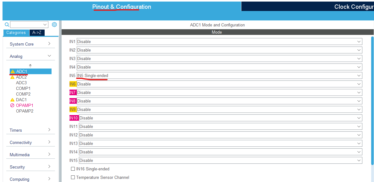
In the Configuration pane, expand Analog → ADC1 and and set IN5 to IN5 Single-ended. PA0 should turn green.
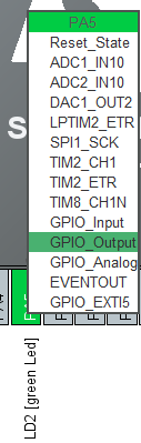
Click on PA5 and ensure that it is set to GPIO_Output.
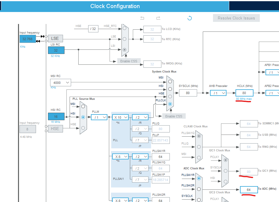
Open the Clock Configuration tab, and check that peripherals (I²C1, ADC1, etc.) are running within valid clock ranges.
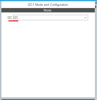
In the Pinout & Configuration tab → under Connectivity, click I2C1.
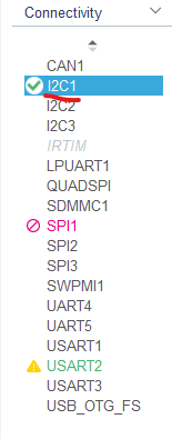
In the Mode window, set I2C to I2C. The PB6 and PB7 pins on the pinout GUI should turn green. After setting Mode → I2C, leave all Parameter Settings alone (defaults are good).
Save and Generate Code.
Program Development
With the pins defined in the .ioc (I²C for the OLED, an ADC pin for the potentiometer, and PC13 for the user button/EXTI), CubeIDE has already generated the boilerplate: clock tree, peripheral inits, and the main.c scaffolding. Now we drop in the application logic—only inside /* USER CODE BEGIN … */ blocks—so regenerating code later won’t nuke our work - trust me that's frustrating, so put the code in the right spots.
What this program will do
Scan I²C at boot to discover the OLED’s address (0x3C or 0x3D are typical)
Initialize the OLED and draw a splash/logo screen.
Sample the potentiometer via ADC, convert to voltage, and show it on an alternate screen.
Update the OLED at a modest rate (e.g., 10 Hz) so we’re not spamming the bus.
File touchpoints
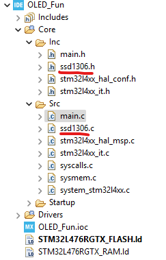
Core/Src/main.c
This is the “director’s chair.” You won’t be writing raw I²C transactions here — you’ll just call high-level functions like
RenderLogo()orRenderADC(). Those in turn lean on the SSD1306 helpers to do the grunt work.Core/Inc/main.h
Used for prototypes or externs if you want to keep global variables and function declarations tidy. Optional, but handy once the project starts growing.
Core/Inc/ssd1306.h& Core/Src/ssd1306.cThis is the helper layer for the OLED. Think of it as a translator between “HAL I²C calls” and “draw something on screen.” Inside here live the routines that:
Send the SSD1306 initialization sequence so the display powers on correctly.
Maintain a framebuffer array in RAM that represents every pixel on the screen.
Offer friendly drawing calls:
ssd1306_clear()→ blank the screen buffer.ssd1306_update()→ send the buffer to the OLED in one go.ssd1306_drawBitmap(x, y, array, w, h)→ paint your logo C array (from Section 1) directly onto the buffer.ssd1306_writeString(x, y, "Hello")→ render text by pulling character bitmaps from a font table
By isolating these in their own files, you avoid polluting main.c with low-level command bytes. The main loop just says “show the logo now” or “print the ADC voltage”, and the helper layer figures out what sequence of I²C packets makes that happen.
0) Pre steps (What we did in .ioc)
I²C1 enabled and pinned to your SCL/SDA (whatever you picked).
ADC1 enabled with one regular channel for the pot (e.g., PA0).
LD2 optional for error blink (leave as output if you want it).
Step 1 — Library Declarations
Open
main.cAdd these files to your project:
ssd1306.his the header file for the OLED helper driver. It declares the functions and constants you’ll use in your application — things likessd1306_init(),ssd1306_clear(),ssd1306_update(),ssd1306_drawBitmap(), andssd1306_writeString(). By including this file inmain.c, you can call those high-level routines without worrying about the low-level I²C command bytes. It also defines the screen dimensions (SSD1306_WIDTH,SSD1306_HEIGHT) so your code knows the display’s resolution.ssd1306.cis the implementation file for the OLED helper driver. It contains the actual code that talks to the SSD1306 controller over I²C — handling initialization, maintaining the screen buffer in RAM, and sending pixel or text data to the display. Functions likessd1306_init(),ssd1306_clear(),ssd1306_update(),ssd1306_drawBitmap(), andssd1306_writeString()live here, turning your high-level draw calls into the proper sequence of bytes the OLED understands.
Step 2 — Include the Logo File
Include the logo file generated from the Image Processing section above. To do this we have to add the file to the Inc folder , (just drag and drop it into the folder) and we need to include it in our main.c code.
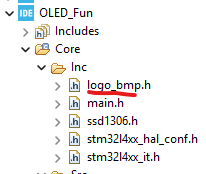
#include "logo_bmp.h"

Step 3 — Globals, Types, and Function Prototypes
This step sets up the project-wide pieces that everything else leans on:
ScreenModeenum — defines two states (SCREEN_LOGO,SCREEN_ADC) so we can flip between screens.g_screenMode— the actual variable holding the current mode (starts on logo).g_lastChangeMs—“activity timer,” refreshed whenever the pot moves enoughg_lastAdcCounts— baseline value, so we can measure deltas.ADC_DELTA— baseline value, so we can measure deltas.g_oledAddr— holds the OLED I²C address (default 0x3C, some modules use 0x3D).
And we declare a few function prototypes so the compiler knows what’s coming later:
RenderLogo()— clears the OLED and draws the splash bitmap.RenderADC()— reads the potentiometer voltage and prints it.ErrorBlink()— flashes the onboard LED if something goes wrong.ProbeOledAddress())— makes startup robust to OLEDs shipping at0x3Cvs0x3D.AdcCountsToVolts()— neat little math helper (keepsRenderADC()tidy).CheckAdcForChange()— called in the main loop to detect when the pot moved enough to warrant switching toSCREEN_ADC.
Step 4 — Main Function Skeleton
This is where all the pieces come together for the first time. The code in step one is auto generated, so just confirm that those pieces are there. The
main()function provides the program’s backbone:System bring-up (Auto generated)
Call
HAL_Init()andSystemClock_Config()to get the MCU running.Initialize peripherals through the Cube-generated functions (
MX_GPIO_Init(),MX_I2C1_Init(),MX_ADC1_Init(), etc.).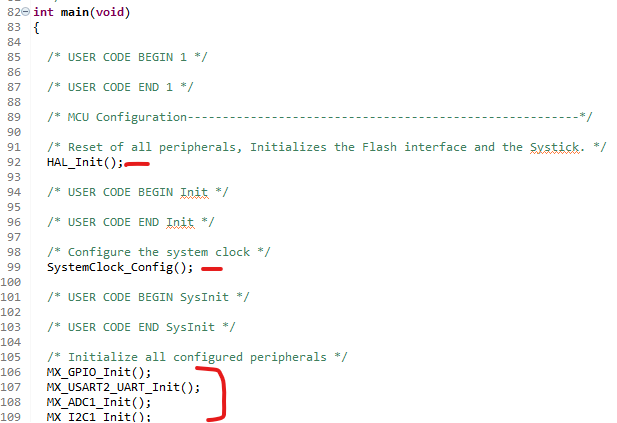
OLED startup
Probe for the OLED’s I²C address (
ProbeOledAddress()), since different modules ship with either0x3Cor0x3D. This code should be placed just after the MX_XX_init() function calls, in the USER CODE BEGIN 2 section.Initialize the OLED with
ssd1306_init().This shold go right under the previouse code, in the same section.Immediately show your splash screen by calling
RenderLogo()so the user sees something on power-up. This should be placed right after the ssd1306_init code, in the same section.
Main loop
Once everything is initialized, the program lives inside the
while(1)loop. Here, a simpleswitchong_screenModedecides what the OLED should show:SCREEN_LOGOcaseThe display already holds the splash screen, so we don’t need to redraw it every cycle.We just poll the ADC lightly with
CheckAdcForChange(). If the potentiometer moves far enough (beyondADC_DELTA), this function flips the mode toSCREEN_ADCand records the time of change.Otherwise, the loop idles with a short
HAL_Delay(50)to keep things responsive without hogging the CPU
SCREEN_ADCcaseThe OLED is actively updated with the current ADC reading every ~100 ms using RenderADC().CheckAdcForChange() continues running in this mode as well, so the “last activity” timer refreshes as long as the knob keeps moving.If no significant ADC change occurs for about 4 seconds (checked with
HAL_GetTick()vs.g_lastChangeMs), the code switches back toSCREEN_LOGOand immediately redraws the splash screen.
Default case
A safety net: ifg_screenModesomehow takes on an invalid value, reset it back toSCREEN_LOGOand redraw the splash.
Step 5 — Function Definitions
Place these function defintions in the /* USER CODE BEGIN 4 */ section, near the bottom.
RenderLogo()– clear, drawlogoBitmapfromlogo.h,ssd1306_update().RenderADC()– read ADC once, compute volts withAdcCountsToVolts(), print lines,ssd1306_update().AdcCountsToVolts()–(vref * counts) / fullscale(4095 for 12‑bit).CheckAdcForChange()– poll ADC, ifabs(delta) >= ADC_DELTA, setg_screenMode=SCREEN_ADCand refreshg_lastChangeMs.ProbeOledAddress()– try 0x3C/0x3D; return found address or 0 on fail.ErrorBlink()– flash PA5 (LD2) on failures.
Code WalkThrough (What, Why, and How)
CubeIDE generates the basic STM32 startup framework, and your application logic runs on top of it. In main(), HAL_Init() resets peripherals, sets up the HAL layer, and starts the SysTick millisecond timer used by HAL_Delay() and HAL_GetTick(). Next, SystemClock_Config() configures the PLL and bus clocks so the CPU and peripherals run at the correct speeds, and the MX_*_Init() functions apply the .ioc configuration for GPIO (LD2 LED), USART2, ADC1, and I2C1. Since the OLED is on I2C, your code immediately probes the bus to find the SSD1306 at a common address (0x3C or 0x3D) using HAL_I2C_IsDeviceReady(); if neither address responds, the firmware calls ErrorBlink() to flash LD2 and then halts in an infinite loop so the failure is obvious rather than silent.
Once the OLED is detected, the code stores the working address, initializes the SSD1306 driver with ssd1306_init(&hi2c1, g_oledAddr), and draws the splash screen using RenderLogo(). From that point on, the OLED is controlled by a simple two-state screen mode (SCREEN_LOGO and SCREEN_ADC) rather than a button: the logo is the default view, and the ADC/voltage screen appears automatically whenever the potentiometer moves. That “movement detection” happens in CheckAdcForChange(), which performs a single ADC conversion, compares the new ADC count to the previously stored reference count (g_lastAdcCounts), and computes an absolute difference; if the difference exceeds a threshold (ADC_DELTA, set to 250 counts), the code treats that as a meaningful voltage change, updates g_lastAdcCounts, switches the display state to SCREEN_ADC, and records the time of the change in milliseconds using g_lastChangeMs = HAL_GetTick().
In the main loop, when the system is in SCREEN_LOGO, it simply polls the ADC occasionally (about every 500 ms) to see if the knob moved; when movement is detected, the state flips to SCREEN_ADC. In SCREEN_ADC, the firmware calls RenderADC() to show the current raw ADC counts and the converted voltage, then checks again for continued movement to keep refreshing the “last change” timestamp. RenderADC() starts the ADC, polls briefly for conversion completion, reads the raw 12-bit count, and converts it to volts using a simple scale (volts = VREF * counts / 4095, with VREF set to 3.3 V), then formats and writes the text to the OLED before updating the screen. While in ADC mode, the display refresh pacing is slowed with a delay (about 1.2 s), and if the code detects that there has been no significant ADC change for a few seconds (it checks whether HAL_GetTick() - g_lastChangeMs has exceeded a timeout), it automatically switches back to SCREEN_LOGO and redraws the splash bitmap. The end result is a UI that feels “automatic”: the logo sits there until the potentiometer voltage changes, the ADC/voltage screen appears while you adjust the knob, and once the input settles for a while, it falls back to the logo without any button presses.
Test It!
Alright — time to flash the Nucleo and see if your tiny OLED slave actually obeys. Hit Run, let CubeIDE program the board, and the SSD1306 should come to life: you’ll get the logo on boot, then the display flips over to a live voltage readout as the ADC input moves from mid → high → low. Once the voltage settles for about a second, it automatically snaps back to the logo like nothing happened.
This is bigger than “look, text on a screen.” It’s proof your whole chain is working: I2C is talking, the OLED init sequence is correct, the ADC is sampling, and your code is smart enough to react to real-world changes instead of just looping in circles. And if you want to see it in action instead of taking my word for it, the YouTube Short embedded below shows the display cycling through the voltage levels in real time.
Good luck on your endeavors!