
Meet the MSP430 USCI Module
The Universal Serial Communication Interface (USCI) is a powerful hardware module built into the MSP430G2553. It handles the low-level details of serial communication, so you don’t have to bit bang like a crazy person.
The G2553 includes two distinct USCI modules, each specialized for different protocols:
USCI_A0: Supports UART (used to talk to a PC over serial) and SPI
USCI_B0: Supports I²C (used to talk to sensors, displays, etc.) and SPI
Each module has its own dedicated set of control and data registers, like:
UCA0TXBUFandUCA0RXBUFfor transmitting and receiving characters over UARTUCB0CTL1,UCB0I2CSA, andUCB0TXBUFfor managing I²C communicationUCAxBR0,UCAxBR1, andUCAxMCTLfor setting baud rates and modulation
Because these modules are hardware-driven, your code only needs to configure a few registers and load or read data — the USCI takes care of the rest.
Best of all, the two modules work independently, so you can use UART on USCI_A0 and I²C on USCI_B0 at the same time — giving your MSP430 serious multitasking ability for real-world embedded systems..
In this two-part tutorial, we'll explore both "flavors" of the USCI module on the MSP430G2553 by building two classic "Hello World" projects. In Part 1, we'll use USCI_A0 to send a message over UART to a PC terminal, demonstrating how to configure the UART registers and establish basic serial communication. In Part 2, we'll switch to USCI_B0 to communicate with an I²C LCD, showing how to send data over the I²C bus and display a message on a physical screen. Together, these projects will give you a practical introduction to the MSP430's built-in serial communication capabilities — both digital and visual.
Part 1: The UART USCI_A
UART (Universal Asynchronous Receiver/Transmitter) is one of the simplest and most widely used serial communication protocols. It allows two devices to send and receive data over just two lines: TX (transmit) and RX (receive) — no clock signal needed. UART is perfect for sending text between a microcontroller and a PC, making it a great first step in learning how to communicate with external devices.
On the MSP430G2553, UART communication is handled by the USCI_A0 module — one of two serial interface engines built into the chip. This module takes care of formatting, timing, and buffering the data, so you only need to configure a few registers and feed it bytes.
In this tutorial, we’ll use the USCI_A0 module to send a simple "Hello, world!" message from the MSP430 to your computer over UART. You’ll connect the MSP430 to your PC using a USB-to-Serial adapter, and use a program like PuTTY to view the message on your screen.
PuTTY is a free and lightweight terminal emulator that lets your computer "listen" to serial ports. Once connected to the correct COM port at the right baud rate (9600 bps), it will display anything the MSP430 sends — making it perfect for testing UART output. If you don't have putty installed on your system you can get it for free here.
By the end of this tutorial, you’ll understand how to set up UART on the MSP430, write directly to the USCI registers, and send real data over a serial line to your PC. Below is the USCI_A Module block diagram in UART mode. Note their are only two lines UC0RX (Receive) and UCOTX (Transmit). These lines are located on pins P1.1 and P1.2.

To get the MSP430G2553 talking over UART, we need to configure a handful of registers in the USCI_A0 module. The first and most important is UCA0CTL1, which controls the state of the USCI module. We begin by putting the USCI into a software reset state (UCSWRST) so we can safely configure it. In this same register, we also select the clock source for the baud rate generator—SMCLK in our case—by setting the UCSSEL_2 bits.
Next, we set the baud rate using UCA0BR0 and UCA0BR1, which together define the division factor for the UART bit timing. For a 1 MHz clock and a target of 9600 baud, these are typically set to UCA0BR0 = 104 and UCA0BR1 = 0. The UCA0MCTL register further fine-tunes the baud rate using modulation (in our case, UCBRS0 is set for small adjustments). Once configuration is complete, we clear the software reset bit in UCA0CTL1, allowing the USCI state machine to start running. Data is sent by writing to UCA0TXBUF, and we check if it's ready using the UCA0TXIFG flag inside the general-purpose IFG2 register. These few registers are all it takes to initialize UART and begin transmitting data from the MSP430 to your PC.
Before you start feeling overwhelmed by all the configuration bits inside the USCI module, take a breath — using UART on the MSP430 is actually pretty simple. While the USCI_A0 module has quite a few registers, you only need to work with a handful of them to get UART up and running. The rest are for more advanced features (like SPI or infrared communication), which we won’t touch in this basic "Hello, world!" example.
UCA0CTL1 – USCI_A0 Control Register 1: This is the first register we touch, and it’s critical. It controls the software reset (
UCSWRST) that lets us safely configure the module. It’s also where we pick the clock source for the UART baud rate generator — typically SMCLK, usingUCSSEL_2.UCA0BR0 and UCA0BR1 – Baud Rate Registers: These two registers define the divisor used to slow down the clock signal to match your desired baud rate (usually 9600 bps). Since the clock runs at 1 MHz in this tutorial, we set
UCA0BR0 = 104andUCA0BR1 = 0, which gives a divisor of 104.UCA0MCTL – Modulation Control: This register fine-tunes the baud rate using a modulation stage. We don’t need anything fancy here — just set
UCBRS0, which provides a small timing correction for better accuracy when dividing 1 MHz into 9600 baud.UCA0TXBUF – Transmit Buffer: This is where you write a single character to send it over UART. Once the transmit flag is set, you drop a byte into
UCA0TXBUF, and the USCI module handles the restIFG2 – Interrupt Flag Register (Contains UCA0TXIFG): We don’t use interrupts in this example, but we still check this register’s flag bit
UCA0TXIFGto know when the transmit buffer is ready. It ensures we don’t try to send another character before the last one is done.
That’s it — just a few well-behaved registers and you’re up and talking to the outside world. The USCI_A0 module is extremely capable, but the basics are straightforward when you stick to the essentials. And because we’re only using UART mode, we don’t have to worry about the SPI-related bits in UCA0CTL0, or any of the special modes in UCA0STAT or UCA0ABCTL.
As always, make sure your UART pins (P1.1 and P1.2) are configured properly. With that, you're good to go. Below is an image showing the jumper wires needed to configure P1.1 and P1.2 properly, so UART communication with your computer can happen - don't stop the magic! Note the sideways jumper positions.

The UART "Hello World" Code and Program Flow
What This Code Does!
This example uses the USCI_A0 module on the MSP430G2553 to send and receive data over a UART connection with a PC. When the program starts, it prompts the user to enter their name using a serial terminal (like PuTTY). Once the user types their name and presses Enter, the MSP430 replies with a friendly greeting — "Hello, [Name]!" — over the same serial connection.
All of the communication happens using hardware-level UART: the USCI module handles baud rate timing, buffering, and character-level transmission. We configure the module for 9600 baud using SMCLK, and use simple polling (not interrupts) to send and receive data one character at a time. The terminal interface provides a basic but useful way to interact with the MSP430 — great for debugging, data logging, or just getting started with serial communication.
Equipment You Need
MSP-EXP430G2ET Development Kit
MSP430G2553
Open Putty Terminal
Before you open the Putty instnace confirm the COM port your MSP430 is using in the Device Manager.

The FLOW
The program flow for this project is structured into 4 main parts. While it follows the same general layout as the other tutorials, this one focuses on using the USCI_A0 module to set up a basic UART communication channel between the MSP430 and a PC. The user is prompted to enter their name over a serial terminal, and the MSP430 replies with a personalized greeting.
MSP430 library declaration and program definitions
This section includes the standard
<msp430.h>header, along with global variable declarations and function prototypes. In this example, we declare a character buffer to store the user's name and set up helper functions for sending and receiving characters over UART.Function Prototypes
This section lists the function prototypes for the UART helper routines. These include
uart_send_string()to transmit strings,uart_receive_char()to read individual characters, anduart_receive_string()to collect user input into a buffer.Main Routine
Turn off Watchdog Timer
The watchdog timer is disabled at startup to prevent unexpected resets during development or communication delays
Set the clock speed
Loads factory calibration constants to configure the digitally controlled oscillator (DCO) for 1 MHz. This clock is used as the timing source for the UART baud rate generator.
Set Up the USCI_A0 Module
The UART module is configured by putting the USCI into reset (
UCSWRST), selecting SMCLK as the clock source, setting the baud rate registers (UCA0BR0,UCA0BR1), enabling modulation viaUCA0MCTL, and then releasing the reset to begin operation.Send and Receive UART Data
The user is prompted to enter their name. As characters are received one by one, they’re echoed back and stored in a buffer. Once Enter is pressed, the MSP430 sends a greeting using the entered name.
Enter "Forever" Loop
After displaying the greeting, the program enters an infinite loop. No interrupts or low-power modes are used in this basic example — the goal is simply to demonstrate one-time input/output over UART.
Function Definitions
This section includes the implementations of the UART helper functions. These use polling to check flags in
IFG2for transmit (UCA0TXIFG) and receive (UCA0RXIFG) readiness, and move data into or out of theUCA0TXBUFandUCA0RXBUFregisters as needed.
The UART Code
When running the code make sure a putty window is open and connected to the right COM port.
Part 2: USCI_B and an I2C LCD
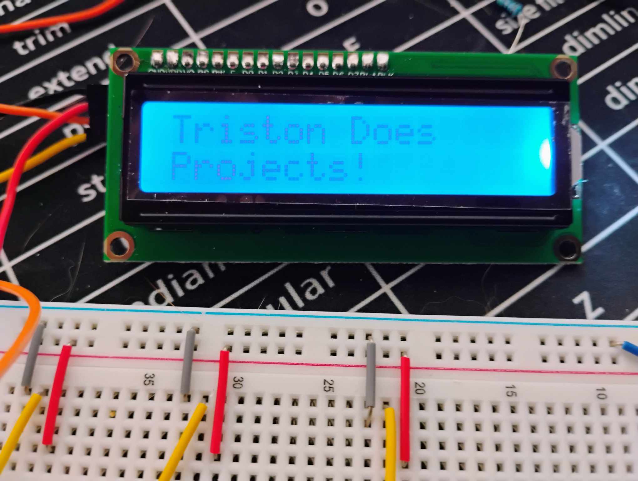
Now that you’ve mastered UART, let’s move on to another essential communication protocol — I2C, and apply it to controlling a standard 16x2 character LCD using only two wires. While UART connects your MSP430 to a PC, I2C allows the MSP430 to talk to peripherals like sensors, EEPROMs, or in this case, an LCD module. It’s a simple but powerful way to expand your projects with minimal pin usage.
Equipment You Need
An 1602 I2C LCD. Just search on Amazon for 1602 LCD I2C and you should find a couple.
MSP430G2553
MSP-EXP430G2ET Development Kit
The 1602 LCD is a simple alphanumeric display capable of showing two lines of 16 characters, commonly used in embedded projects for text output. It’s driven by the HD44780 controller, and when paired with a PCF8574 I/O expander, it can be controlled over I²C, reducing the number of required microcontroller pins from 6–10 down to just 2 (SCL and SDA). This makes it ideal for microcontrollers like the MSP430 that have limited I/O. The display features a built-in backlight, adjustable contrast, and supports both 4-bit and 8-bit communication modes under the hood, though the I²C adapter always uses 4-bit mode.
The PCF8574 I/O Expander
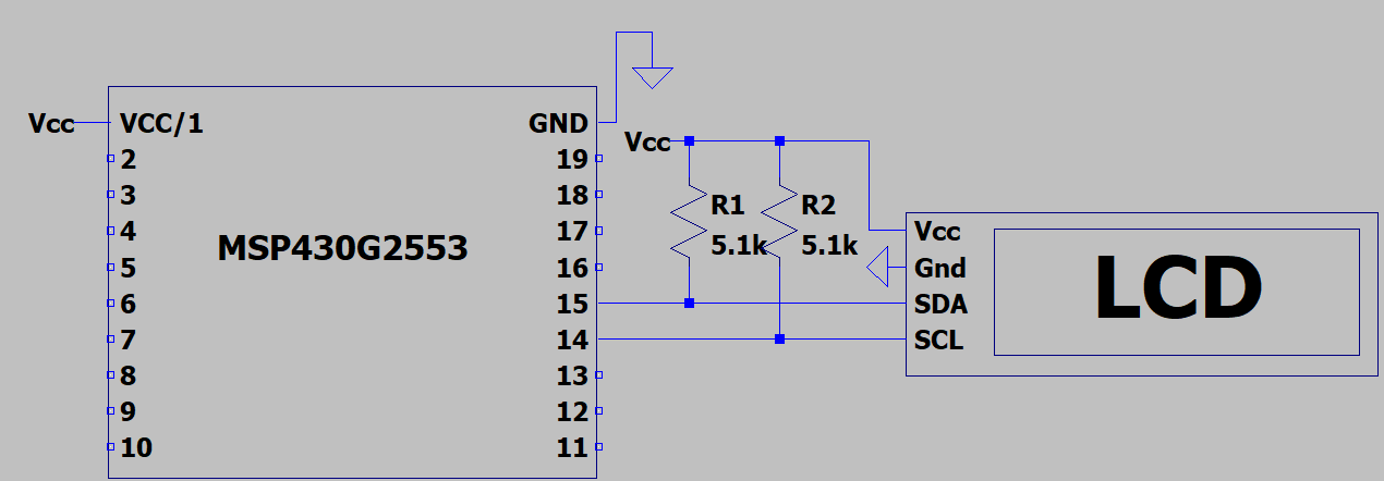
Most 16x2 character LCDs use the HD44780 controller, which requires at least 6 GPIO pins to drive directly. To make things easier, many LCD modules come pre-soldered with a small board based on the PCF8574 I/O expander, which converts I2C signals into the parallel signals the LCD understands. This lets us control the whole display over just two pins: SDA (P1.7) and SCL (P1.6).
The PCF8574 drives the LCD in 4-bit mode, meaning each 8-bit command is split into two 4-bit transmissions — one for the high nibble and one for the low nibble. To make this work, we write each nibble individually, pulse the EN (Enable) bit, and manage the RS (Register Select) bit to switch between command mode and data mode.
The below figure shows a connection to the 1602 LCD to the MSP430. The resistor values can be as low as 2.2k, but will work up to 5.1k easily.
Overview of LCD Initialization
Before printing anything, the LCD must be properly initialized — otherwise, you’ll see garbage characters or nothing at all. The initialization sequence configures the LCD in 4-bit mode, sets the number of display lines, turns on the display, and clears any old data. This is done by manually sending the 0x30 command three times (full 8-bit initialization mode), followed by 0x20 to switch to 4-bit mode. After that, we can use regular commands like 0x28 (4-bit, 2-line mode), 0x0C (display ON, cursor OFF), 0x06 (auto-increment cursor), and 0x01 (clear display)
Here’s what’s happening under the hood:
Writing Characters and Strings
To write a character, we send its ASCII value with RS set to 1 (data mode). To write a command, we set RS to 0. Strings are simply written as a loop over characters using lcd_write_string(), which repeatedly calls lcd_send_byte() for each character.
The cursor is controlled by writing to specific addresses:
0x80moves the cursor to the first line0xC0moves it to the second line
I2C Setup on the MSP430G2553
The MSP430 handles I2C communication via USCI_B0, configured similarly to UART. We enable SMCLK as the clock source, set the baud rate to ~100kHz (12-bit divisor), and release the software reset to activate the I2C engine. Each byte of LCD data is sent using UCB0TXBUF, while polling status flags in IFG2.
Here are the key registers used:
Why This Matters
Using I2C to control an LCD not only saves GPIO pins, but it also mirrors real-world embedded applications — where I2C is often the go-to interface for displays, sensors, and other smart devices. By learning how to drive an I2C LCD manually, you get full insight into how bit-level communication works behind the scenes, including bus timing, byte formatting, and handshake procedures.
The FLOW
This project follows a familiar 4-part structure seen in the other MSP430 tutorials. The focus here is on interfacing with a 1602 LCD over I²C using the USCI_B0 module and sending initialization commands in 4-bit mode through a PCF8574 I/O expander.
MSP430 Library Declaration and Global Variables
The program begins by including the standard
<msp430.h>header, followed by#definemacros for LCD-specific control bits (RS, EN, BACKLIGHT), the LCD’s I²C address, and a character buffer used for holding display strings.Function Prototypes
This section declares all function prototypes used in the program:
i2c_init()configures the USCI_B0 module for I²C Master mode.lcd_send_byte()sends a byte (data or command) to the LCD using a high nibble / low nibble split.lcd_command()sends command instructions (e.g., clear, cursor control).lcd_write_string()prints a C-style string to the LCD.lcd_init()walks through the full LCD power-up sequence per datasheet.
Main Routine
The main function is broken down into four substeps for clarity and consistency.
Turn Off the Watchdog Time
Disables the WDT using
WDTCTL = WDTPW | WDTHOLD;to prevent unexpected resets during execution.Set the Clock Speed
Initializes the digitally controlled oscillator (DCO) to run at 1 MHz using factory calibration constants. This frequency becomes the source for the I²C clock.
Set Up I²C and LCD
Initializes the USCI_B0 module in I²C Master mode at ~100kHz, then performs a full LCD initialization sequence using a 4-bit interface via the I/O expander. This sequence includes:
Power-on delays.
Sending
0x30three times.Switching to 4-bit mode (
0x20).Sending function set, display control, entry mode, and clear display commands.
Display Content and Enter Forever Loop
The LCD cursor is positioned using commands (
0x80for line 1,0xC0for line 2), and text strings are loaded into the global character buffer usingstrcpy()and printed usinglcd_write_string(). The program then enters an infinite loop, leaving the LCD display active with no further updates
Function Definitions
This section includes all helper function implementations.
i2c_init()maps pins P1.6 and P1.7 to I²C (SCL, SDA), configures USCI_B0, and sets baud rate.lcd_send_byte()breaks the 8-bit command or data byte into two 4-bit nibbles and sends each with the proper enable pulse over I²C.lcd_command()sends a byte with RS=0.lcd_write_string()loops through the characters of a C string and sends them as data (RS=1).lcd_init()implements the complete power-on reset and mode configuration for the LCD, per theHD44780timing spec andI²Cadapter protocol
The I2C LCD Code
All Tutorials Must End
When I first started working with the USCI module, it felt a bit like a black box—UART, I²C, SPI... all packed into one interface, each with its own quirks and registers. But once you separate the two modules (USCI_A0 for UART and USCI_B0 for I²C) and walk through a real-world example for each, the fog clears up fast. Sending a simple message to a terminal and getting text to appear on an I²C LCD are great stepping stones into embedded communication. This isn’t meant to be a deep-dive into every protocol feature, but a practical walkthrough to help you get your MSP430 talking to the outside world. If you get stuck or something’s not behaving the way you expect, feel free to reach out — I’m happy to help. Good luck, and keep building!