
Ghetto DAC
Digital is great and all—zeros and ones, clean signals, precise logic—but when you want to wiggle electrons in a graceful, sine-wavy fashion, you're going to need to fake your way into the analog world. Enter the Ghetto DAC: a janky yet beautiful concoction of pulse width modulation, an RC filter, and pure spite for overpriced DAC chips. This project takes your MSP430G2553 and turns it into a half-decent waveform generator, entirely on the cheap.
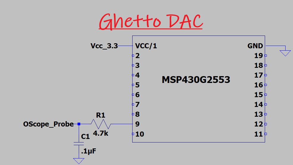
The only parts you’ll need are what’s shown in the picture above - THAT’S IT!
Project Scope
This project aims to build a functional Digital-to-Analog Converter (DAC) using nothing more than the MSP430’s built-in Timer A module, a simple resistor-capacitor (RC) filter, and some carefully crafted C code. No fancy peripherals, no external DAC chips—just raw timer-based PWM filtered into submission. The end goal? A voltage waveform that actually looks analog on an oscilloscope and could even pass as a sinewave if you squint hard enough.
We'll explore how pulse width modulation can approximate analog voltage levels by varying duty cycles, how an RC low-pass filter smooths those pulses into a continuous signal, and how the timing, resolution, and component selection all come together to define the quality of your output. You'll also get a walkthrough of a working code example with a sinewave lookup table (LUT), plus tools to tweak your waveform resolution and filter characteristics.
This isn’t just a proof of concept—it’s a framework you can reuse, expand, or duct-tape into more complex analog output projects like signal generators, audio toys, or even control signals for more sophisticated analog circuits. We’re not building a precision instrument here—we’re building a scrappy DAC that works, and that’s the whole point.
Tools (Equipment, Parts, and Software)
MSP-EXP430G2ET Development Kit
MSP430G2553
4.7k Resistor
.1uF Capacitor
Ocsilliscope
Implementation (The How)
Digital is cool and all, but let’s be honest — digital abstraction is just analog wrapped up in binary foolery! So let’s take this binary bore and launch it into continuous space with all the precision a $3, 16-bit MCU can muster.
Now, there are more than a few ways to turn digital signals into analog ones. In this exercise, we’re going to keep it “simple” and create our analog signal using pulse width modulation (PWM). We previously explored this in the ADC tutorial, where we recreated the voltage seen by the ADC on another pin using a resistor and a capacitor. Here, we’re doing basically the same thing — but instead of following an ADC register, we’ll cycle through a lookup table (LUT).
Why The RC Choice Matters
The Ghetto DAC’s performance is tied to two key parameters: the RC combination and the frequency of the PWM signal. The RC pair connected to the MCU pin is nothing more than a low-pass filter — which, if you squint at it just right, can be thought of as a poor man’s integrator. The cutoff frequency of our little integrator is:
This is the frequency at which the capacitor impedes current flow just as much as the resistor. In addition, the RC time constant determines how smooth our signal will be. If the RC time constant is too slow, it won’t be able to keep up with the PWM signal to produce our analog masterpiece. On the other hand, if it’s too fast, it won’t smooth the waveform enough—and we’ll be stuck back on the digital side.
Life is all about balance—and it turns out the Ghetto DAC needs it too. To maintain this balance, we have to ensure that our RC time constant is slow enough to hold the average of the PWM signal for a moment, yet fast enough to keep up with the signal we want to generate. Words are hard, equations are to the point:
If we stay within this sweet spot, we'll be all kinds of happy. This is a pretty crucial expression, as it ties all our bits together—it relates our RC time constant to our PWM frequency and our generated sinewave masterpiece.
Frequency Tie Into Timer A
The frequency of our PWM signal is directly tied to the Timer A clock frequency, which we’ll max out at 16 MHz for optimal response. You can calculate this frequency using the expression below.
And now we have one more frequency to worry about—our generated sinewave frequency. This one’s pretty straightforward, even after a bit of whiskey. Just divide the Timer A clock frequency by the product of the Timer A counter period, the STEP_DELAY, and the size of the LUT. Voilà:
LUT Generation
So the “magic” behind this Ghetto DAC is all about carefully applied duty cycles. We make this happen using a Lookup Table (LUT) and the Timer A module. I’ve already written a tutorial on the Timer A module — go check it out if your clueless alarm is going off. It’s okay, we’ve all been there. Heck, maybe I’m there right now.
Below is the equation I used to come up with these magical LUT values:
Where:
MAX_DUTY is the size of the value sorted in the TA1CCR0 register
NUM_SAMPLES is the size of the LUT
Of course, you don’t want to apply said equation over and over again to come up with said LUT values. I certainly didn’t. However, these LUT values are tied to the pulse width and the sample size of said Ghetto DAC. Below is a tool that will give you a LUT in C for a given NUM_SAMPLES and MAX_DUTY.
The Code FLOW
This is a pretty straightforward program — all we’re doing is setting up the Timer A module to output a PWM signal. The duty cycle of this PWM signal varies according to the LUT, and when it’s run through an RC filter, we get a “smooth” signal .
There are three variables you can tweak to tune the sine wave to your desired frequency: MAX_DUTY, STEP_DELAY, and NUM_SAMPLES. In the code below, these values are set to produce a sine wave of about 24 Hz. If you change them, the frequency will change.
The program flow for the Ghetto DAC is structured into four key parts: Part 1 covers library declarations, definitions, and global variables; Part 2 is for function prototypes (none in this case); Part 3 is the main function, which contains subsections that set up the magic; and Part 4 contains the ISRs and function definitions.
Part 1: MSP430 Library Declaration and Program Definitions
This section includes the standard
<msp430.h>header along with relevant preprocessor macros. Here we define:The PWM output pin (P2.1 mapped to TA1.1)
The maximum duty cycle (1023 for 10-bit PWM resolution)
A step delay constant, which controls how long each voltage level is heldA step delay constant, which controls how long each voltage level is held
The sinewave lookup table that defines a full cycle of PWM duty steps to simulate a waveform
Global variables to track the current index and delay state for smooth waveform generation
Part 2: Function Prototypes
There are no custom user-defined helper functions in this project, so this section is minimal. However, it remains in place for structure and easy expansion in future iterations.
Part 3: Main Routine
Step 3.i — Turn off the Watchdog Timer
Disables the watchdog timer to prevent unwanted resets during development and testing.
Step 3.ii — Set the Clock Speed
Loads factory calibration values to configure the DCO to 16 MHz. This ensures a stable timing base for the PWM generator (Timer1_A)
Step 3.iii — Setup Timer A1 for PWM
Configures the TA1.1 output:
P2.1 is set as output and connected to TA1.1 function
Timer1_A is set in up mode, using SMCLK
The timer is configured with OUTMOD_7 (reset/set), which produces a clean PWM waveform
Initial duty cycle is loaded from the lookup table (starts at 1V equivalent)
The Timer1 overflow interrupt is enabled to manage waveform stepping through the LUT.
Step 3.iv — Enter the Forever Loop
The main loop simply idles with
__no_operation();. All logic is handled inside the Timer A interrupt service routine, allowing precise and predictable timing of waveform updates without constant CPU involvement.
Part 4: ISR(s) or Function Definitions
Timer1_A1 ISR (Overflow Handler)
This interrupt is triggered when Timer1_A reaches the end of its PWM period. It performs these key tasks:
Increments a software delay counter. Only when this counter reaches
STEP_DELAYdoes the waveform advance to the next step.Cycles through the lookup table using modular arithmetic:
stepIndex = (stepIndex + 1) % NUM_STEPS;
The updated value is written to TA1CCR1, which changes the PWM duty cycle. The RC filter on the output then smooths the PWM into a voltage level that approximates a DAC output.
The Ghetto DAC Code
Freqeuncy Tuning
Below is an RC Tuning Tool for the Ghetto DAC code. Enter the frequency you want to generate along with the other parameters, and it will spit out the resulting frequency. Keep in mind that as you increase the target frequency, you’ll need to reduce the MAX_DUTY value, and both the LUT size and STEP_DELAY will likely need to be decreased as well.
Also, if you change the MAX_DUTY value, you will need to use the LUT Generation tool above to create a new LUT. Likewise, if you change the number of LUT elements, this tool will be required as well!
The gallery showcases four oscilloscope captures from the Ghetto DAC, each highlighting how frequency and RC tuning interact with the STEP_DELAY parameter. The first image, at 1.024 kHz with a STEP_DELAY of 15, and the second, at 502 Hz with a STEP_DELAY of 2, were generated using different RC combinations, showing how filter characteristics shape the output at higher speeds. The third image, at 33 Hz with a STEP_DELAY of 15, and the fourth, at 488 Hz with a STEP_DELAY of 1, used the same RC combination but different STEP_DELAY values, illustrating how this parameter alone can dramatically shift the waveform’s smoothness and frequency while keeping the hardware filter constant.
| Parameter | Value |
|---|
Outcome (Does It Work)
The table below brings some well-deserved science to the madness. It compares the measured sinewave frequency (captured with an oscilloscope) against the calculated frequency using our glorious formula that ties together MAX_DUTY, STEP_DELAY, and the size of the sine lookup table. With MAX_DUTY fixed at 1023, the only knob we're turning is STEP_DELAY, and you can see the resulting frequency plummet as STEP_DELAY increases. The fact that the measured values track closely with the calculated ones means we're not just guessing—we’re actually doing engineering here. What a concept.
THE END
Look, is this the prettiest DAC in the world? No. Not even close. It’s called the Ghetto DAC for a reason. But did it work? Hell yes it did.
We wrangled a crusty little PWM signal from the MSP430, shoved it through an RC filter, and somehow convinced it to pretend it was analog. Was it elegant? Nope. Was it clever? Absolutely. No op-amps, no DAC peripherals, just raw timer register manipulation and a resistor that’s probably older than your soldering iron.
And yeah, the output kind of looks like a sine wave... until you speed it up too much and it starts melting like a popsicle in July. That’s just physics being rude — RC filters can only do so much before they start throwing up on the sidewalk. We saw it. We lived it. We scoped it.
But if you squint hard enough at the waveform and sip your coffee (or something stronger), you’ll see it: a DAC born from nothing but digital pulse abuse and timing wizardry. A waveform you pulled out of thin air using only 16-bit'ish PWM and sheer determination.
Is it janky? Oh yes.
Is it yours? Damn right.